Solved Given V 6 V, What Is The Current Of The Ideal Current
Di: Ava
The article explains the theory of ideal transformer, including their operating principles, voltage and current relationships, and associated losses, supported
In the circuit shown, assume that the op-amp is ideal. If the gain (v
The current-voltage characteristic of an ideal \ (\mathrm {p \text {-}n}\) junction diode is given by the graph as shown in the following figure: This diode is connected with a resistance of \ (5~\Omega\) in series with it as shown below: Which of the following shows the dependence of the voltage \ (V_ {AB}\) and the current \ (i,\)when the Engineering Electrical Engineering Electrical Engineering questions and answers Problem 1: For the circuits shown in below, using ideal diodes, find the values of the voltages and currents indicated. +5V 10 kn 10 kn 小文 V V * 10 kn 10k Problem 2: For the circuits shown in below, using ideal diodes, find the values of the labeled voltages and currents SV +IVO +2 Vo OV 2 kn * D 2
A 45-mH ideal inductor is connected in series with a 60-Ω resistor through an ideal 15-V DC power supply and an open switch. If the switch is closed at time t=0s, what is the current 7.0 ms later?
The current-voltage characteristic of an ideal \ (\mathrm {p \text {-}n}\) junction diode is given by the graph as shown in the following figure: This diode is connected with a resistance of \ (5~\Omega\) in series with it as shown below: Which of the following shows the dependence of the voltage \ (V_ {AB}\) and the current \ (i,\)when the We transform this dependent current source as well as the 6 V independent voltage source as shown in Figure. (6a). The 18 V voltage source is not transformed because it is not connected in series with any resistor. In the circuit shown below, the knee current of the ideal Zener diode is 10 mA. To maintain 5 V across R L, the Minimum value of R L in Ω
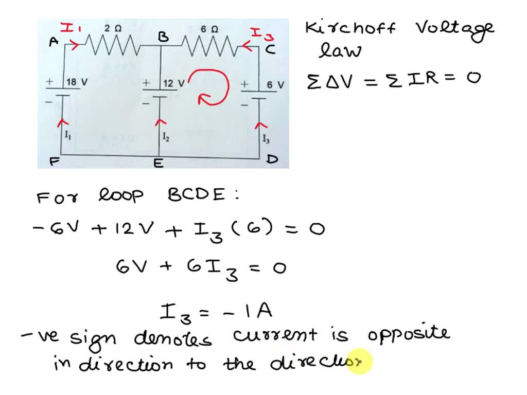
Question: Referring to the given figure where V-6 V, use source transformation to determine the current and power absorbed by the 8-2 resistor. 8Ω 3Ω 3 A 10Ω 6Ω 1.7 A The current absorbed by the 8-Ω resistor is The power absorbed by the 8-2 resistor is23.12 W If base current is removed causing the transistor to turn off, V CE (max) will be exceeded because the entire supply voltage V CC will be dropped across the transistor.
Solved Problems on Source Transformation
For the circuit shown below, taking the Op-amp as ideal, the output voltage V o u t in terms of the input voltages V 1, V 2 a n d V 3 is Ohm’s Law with Examples Ohm’s Law Ohm’s law states that the voltage V across a conductor of resistance R is proportional to the current I passing through the resistor (see circuit below). The relationship is written as: V = R I Which can also be written as I = V R and R = V I. The units are in Volts (V) for the voltage V, Amperes (A) for the current I and Ohms (Ω) for the resistance of
Question: If emf of the ideal battery is V = 4.0 V, what is the current through R6 for the circuit shown in the figure? A) 0.040 A B) 0.0077 A C) 4.0 A D) 0.017 A
- [Solved] For the circuit shown in the figure assume ideal diodes with
- [Solved] As per the given circuit, the value of current through the b
- [Solved] In the circuit D1 & D2 are ideal diodes. The current I1
- Solved Problems On Zener Diode
For the circuit shown in the figure assume ideal diodes with zero forward resistance and zero forward voltage drop. The current through the diode D 2 in mA is ___________.
Concept: An ideal op-amp follows the virtual ground concept, i.e. the positive and negative terminals of the Op-amp remains at the same potential: V + = V – Also, the Inputs terminals current of an ideal opamp is zero. Calculation: Using KCL at the negative terminal of the Opamp, we can write: V 1 V 2 R = V 2 2 R + V 2 V 0 3 R On By ideal we mean, we will ignore the barrier potential of the diode that is 0.7v in case of silicon and 0.3 v in case of germanium when it is forward biased. So, when diode is forward biased, we will say infinite amount of current is If you have considered all energy sources are ideal sources, you need not consider internal resistance. And directly short-circuit voltage source and open-circuit current source. But in case, if internal resistance of sources is given, you have to replace internal resistance. Step-3 Now, in a circuit, only one independent energy source is present.
Mesh Current Analysis or Method Explained with Examples
Most commonly, we use Ohm’s law, Kirchhoff’s law to solve complex electrical circuits, but we must also be aware that there are many circuit analysis theorems using which we can calculate the current and voltage at any given point in a circuit. Among the various circuit theorems, Thevenin’s theorem is most commonly used. In this article, let us learn about Thevenin’s Q. 4 In the circuit shown below, the knee current of the ideal Zener dioide is10 mA . To maintain 5 V across RL , the minimum value of RL in W and the minimum power rating of the Zener diode in mW , respectively, are (A) 125 and 125 (C) 250 and 125 (B) 125 and 250 Find the value of current flowing through AB is Solution The barrier potential of the diode is neglected as it is an ideal diode. The value of current flowing
- Solved Problems on Transistor Biasing
- Thevenin’s Theorem Explanation
- Mesh Current Analysis or Method Explained with Examples
- Solved If emf of the ideal battery is V = 4.0 V, what is the
For an ideal current source, the larger the load resistor, the more work they have to do since they must generate a larger voltage for a given current. Current sources prefer small load resistors, the opposite of voltage sources. Get free HC Verma Solutions for Concepts of Physics Vol. 2 [English] Class 11 and 12 Chapter 10 Electric Current in Conductors solved by experts. Available here are Chapter 10 – Electric Current in Conductors Exercises Questions with Solutions and detail explanation for your practice before the examination The symmetery of the circuit indicates that a similar limiting value occurs at negative values of vI spcifically when vI 6 −4.65 V when D1 and D4 conduct and D2 and D3 cut off and the circuit reduces to that shown in Figure (3.5).
Given, V CC = 12V, V CE = 8V, I C = 1mA, β = 100, VBE = 0.3V (i) To obtain the required operating point, we should find the value of R B. Now, collector load is (ii) Now β = 50, and other circuit values remain the same. Q16. It is desired to set the operating point at 2V, 1mA by biasing a silicon transistor with collector feedback
Three resistors with resistances of 2.0 Ω, 6.0 Ω, and 12 Ω are connected across an ideal dc voltage source V as shown in the figure. If the total current through the circuit is I = 2.0 A, what is the applied voltage V? 2.7 V Part A Find the current through the 1.0-Ω resistor. Part B Find the current through the 3.0-Ω resistor.
A practical silicon diode with a cut-in voltage of 0.7 V is connected as follows: P-terminal (anode) → Ground (0V) N-terminal (cathode) → +10V Given that the current flowing through the diode is 1 μA, what is the DC resistance in reverse biased diode? Basic electronics Solved problems By Sasmita January 9, 2020 Last Updated on May 20, 2025 by Sasmita Rectifiers are crucial components in electronic circuits that convert alternating current (AC) to direct current (DC). Understanding rectifier behavior through solved problems helps reinforce theoretical concepts and practical Solved Problems On Zener DiodeLast Updated on May 20, 2025 by Sasmita A Zener diode is a special type of diode designed to reliably allow current to flow “backwards” when a certain set reverse voltage, known as the Zener breakdown voltage, is reached. In this article, we explore several solved problems that help in understanding its characteristics and
In the voltage reference circuit shown in the figure, the op-amp is ideal and the transistors Q 1, Q 2,.., Q 32 are identical in all respects and have infinitely large values of common – emitter current gain $$\beta $$. The collector current (I C) of the transistors is related to their base emitter voltage (V BE) by the relation I C = I S exp (V BE /V T); where I s is the saturation Verify Verify that that each each of of the the current current sources sources has has the the minimum minimum required required dc dc voltage voltage across across it it for for proper proper operation. operation. Concept: In a negative feedback op-amp circuit, inverting & non-inverting terminals are considered as short i.e. inverting & non-inverting potential are considered as equal because of virtual short property of an ideal OpAmp. Calculation: Given circuit is redrawn as shown: V – = V + (According to virtual short concept) So V – = V + = 0 1) Applying KCL at inverting terminal (V
Chapter 5, The Operational Amplifier Video Solutions
M1, M2 and M3 in the circuit shown below are matched N-channel enhancement mode MOSFETs operating in saturation mode, forward voltage drop of each diode is 0.7 V, reverse leakage current of each diode is negligible and the opamp is ideal.
A practical silicon diode with a cut-in voltage of 0.7 V is connected as follows: P-terminal (anode) → Ground (0V) N-terminal (cathode) → +10V Given that the current flowing through the diode is 1 μA, what is the DC resistance in reverse biased diode? Question: In the figure R1 = 6.52 Ω, R2 = 19.6 Ω, and the ideal battery has emf ε = 13.9 V. (a) What is the magnitude of current i1? (b) How much energy is dissipated by all four resistors in 1.64 min?
- Solved A Layer Of An Unknown Liquid A (Immiscible With
- Solved: In The Vicinity Of A Bonfire The Temperature T (In
- Solved: Html Cell Background-Color
- Solaire Thermodynamique À Fresnel : Première Mondiale En France
- Solaire Darksouls Praise | Awesome Dark Souls Solaire Wallpapers
- Solved Warninng Message 9031 , Femto Engineering: CAE consulting and software solutions
- Solides Haus Mit Drei Kleinen Wohnungen Nähe Marktplatz.
- Solarban 60 Vs. 70 Low-E Glass: A Detailed Comparison
- Solved: Pen Tool Won’T Stop : Solved: Pencil tool not working Lenovo Active Pen 2
- Some Persian Gulf State Crossword Clue
- Solved: Sims 4 Cas Story Not Completing
- Solved The Velocity Of A Periodic Wave Is Equal To Its