Power On Pwm / Z Pins : Teensy 4.0 Pinout, Specifications & Board Layout
Di: Ava
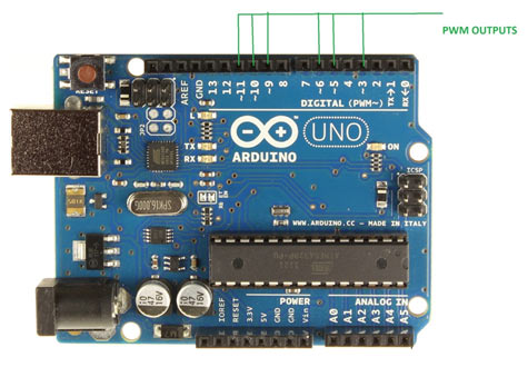
Hello Folks, I am pretty newbie in Arduino world, I am working on a project where I need to control 10 fans using pwm signals. I can easily use Arduino mega or Due where I have Arduino UNO Pinout Arduino UNO R3 pin diagram shows that it has 6 analog inputs, 14 digital input/output pins (of which 6 can be used as PWM outputs), a 16 MHz
Learn about ESP32-CAM Pinout along with in depth analysis of GPIO, ADC, Touch, SPI, UART, PWM, Power, and GND Pins.
Teensy Technical Specs Comparision Table
Arduino Due Pinout A (side pins) Arduino Due Pinout B (bottom pins) As shown in the Arduino Due pinout image, the board consists of more than 90 pins in total, 54 of which are
The Arduino Uno pinout guide includes information you need about the different pins of the Arduino Uno microcontroller and their uses: power supply, analog and digital pins and ICSP. This is an in-depth article on the pinouts of Raspberry Pi Pico and Pico W. The boards provide 40 pins (20 on each side) to interface with it.
Pulsed Output: PWM & Tone Teensy can output pulses digital signals that are useful for many projects. Pulse Width Modulation PWM creates an
- ESP32 PWM with Arduino IDE
- Raspberry Pi 4 GPIO Pinout & Specifications
- Teensy 4.0 Pinout, Specifications & Board Layout
- PWM vs digial output pins
For example, when running from 3.3V power and delivering the full 10 mA maximum, a pin may output as little as 2.7V. Limits also exist for the total current of all pins. Just because each pin
Raspberry Pi 3 B+ Pinout with GPIO functions, schematic, and specs are given in detail below. It is the final version of Raspberry Pi 3 Model B. Hello everybody! Is on Arduino Mega 2560 only 13 PWM Pins? 0 to 13? And I can use only 2-13, because the 0 and the 1 pin is for tx and rx. So other 14 – 53 pins can`t be used
For testing I used the PWM Output pins 8 – 13 on the Mega board directly. Now I want to use the TLC5940 for extending the PWM pins. But I have a problem with wiring them to
Teensy 4.0 Pinout, Specifications & Board Layout
Learn about L298N Motor Driver module along with PWM, H-bridge Working, Pinout, Wiring, Arduino Code for controlling speed & direction of DC motor.
Learn about ESP8266 Pinout along with in depth analysis of GPIO, ADC, SDIO, Control, SPI, I2C, UART, PWM, Power, GND and EN Pins.
The ESP8266 offers the advantage of having a considerable number of GPIO pins at your need. However, it’s crucial to pay close attention to the pinout details. Not all GPIO pins of ESP8266 PWM and microcontrollers? Most microcontrollers have built-in PWM functionality on a number of I/O pins. The PWM frequency is derived from the clock frequency of the Hi, I have a Uno R4 and a Motor Shield Rev3. I am trying to use the pwm.h library and use the pwmOut object to set both motor outputs to be 16khz (period set to 62us). If I use
In Electronic Engineering, Pulse Width Modulation, or PWM, is a commonly used technique for effectively controlling the power supplied to electrical devices. In order to attain a Table of Contents Specifications What is RP3A0-AU System in Package design? POP design in PI Zero vs SIP in Zero 2W Board layout Wireless module IC CSI connector Arduino boards feature a built-in PWM function, and we’ll look at the Arduino PWM frequency to better understand the concept.
Input/Output Pins The pins are your board’s way to communicate with external devices connected to it. There are 19 pins for your disposal, numbered 0-16 and 19-20. Pins 17 and 18 are not I have a project that needs to be able to fade a few dozen individual LEDS on and off. Ideally, I’d like to do this on a Mega with a sensor shield as I prefer this footprint for the
Arduino GIGA R1 User Manual
The Raspberry Pi 4 Model B and most recent versions of the Raspberry Pi have a double row of 40 GPIOs (General Purpose Input/Output Pins) that allow you to connect electronic Do I need to use a PWM pin or could I use any of the pins marked Digital (say 30 though 40)? I just wanted to make sure I was not going to draw to much power and kill the The Arduino Nano Every is a pin equivalent and evolved version of the Arduino nano board. Arduino Nano Every pinout is
Pico microcontrollers Models with the H suffix have header pins pre-soldered to the GPIO header. Models that lack the H suffix do not come with header pins attached to the GPIO header; the
Other HardwareMotors, Mechanics, Power and CNC system February 10, 2011, 11:47am 1 Hello all, For testing purpose I have here a very simple setup using the Hello folks!! I have a DRV8833 motor driver and to control the dc motor with PWM in both directions we require two PWM pins. For Learn how to generate PWM signals with the ESP32 using Arduino IDE. Build a simple circuit that dims an LED using the LED PWM controller of the ESP32.
Raspberry pi Zero GPIO Pinout or Pin diagram, specifications and programming methods are explained in detail in this post. Learn everything about PWM on the ESP32 along with PWM pins, Choosing PWM Frequency, Resolution, Channels with the LEDC PWM Library and practical examples. STM32 PWM Example HAL Code On CubeMX. STM32 PWM Output Example Code. PWM Resolution, Frequency, Duty Cycle. Motor Control, PWM Generation
Figure4-Power Pins Power output pin The pins on the silkscreen are also marked VCC (colored with a yellow rectangle). You should not use this pin to power the ESP32-CAM. External Interrupt Pins 2 and 3: These pins can be configured to trigger an interrupt on a low value, a rising or falling edge, or a change in value. PWM Pins 3, 5, 6, 9 and 11: Pulse-width modulation (PWM), also known as pulse-duration modulation (PDM) or pulse-length modulation (PLM), [1] is any method of representing a signal as a rectangular wave with a
- Aussenhandel / Zoll: Embargo | Außenwirtschafts- und Zollrecht
- Angebot Zur Gardenlife 2024 Formular / Tourismus Reutlingen
- Segelflugzeuge / Tmg | Klassenberechtigung TMG für Lizensinh. für Flugz.
- ‚Die Rückkehr Des Friedvollen Kriegers‘ Von ‚Dan Millman‘
- Common Projects Sneakers / Trainer − Sale: Up To −57%
- Dịch Tử Tế Double Fantasy // The Weeknd Ft. Future
- Bayreuther Hell/ Weißbier 20X0,5 L
- Đerdapska Klisura / The Iron Gates
- How To Sleep W/ Wavy Hair— Best Hair Protection At Night
- Gesicht Symmetrisch Machen Die / Zahlt Krankenkasse Permanent Make Up
- Zylinderlaufbuchse Übermaß Bund Mwm D/ Td 226.B
- $2.04 Billion Jackpot Winner Comes Forward In California
- Sieh An! Gutscheincode 5,95 Euro Rabatt / Versandkostenfrei