Controlling A Stepper Via Mosfets
Di: Ava
(2) DM542 Fully Digital Stepper Driver User’s Manual v1.0 – LeadShine Tech (3) CNC 9-30V DC 128A Stepper Motor Controller, Microstep – AliExpress US$14 (4) Fake microstepping in A4899 stepper-drivers – @GnuReligion, EESE, Asked 2021apr14 (5) What could be the reasons for a stepper motor stuttering with an A4988 driver?, EESE 2021apr05
Pololu High-Power Stepper Motor Driver 36v4
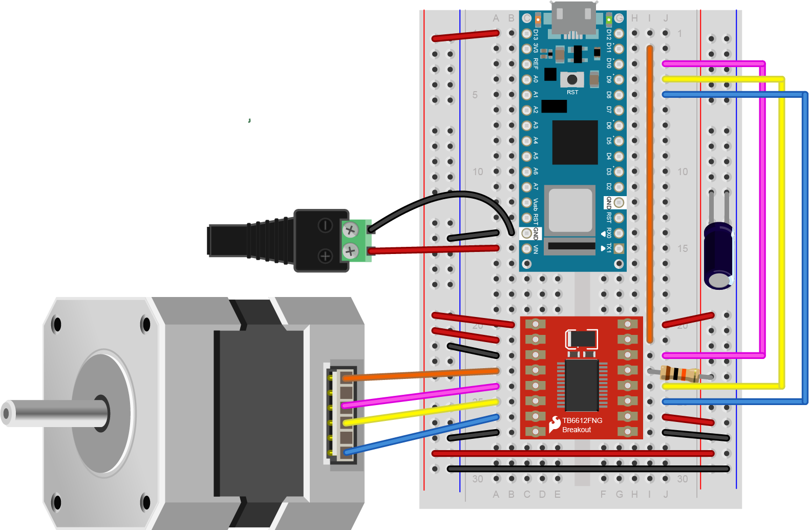
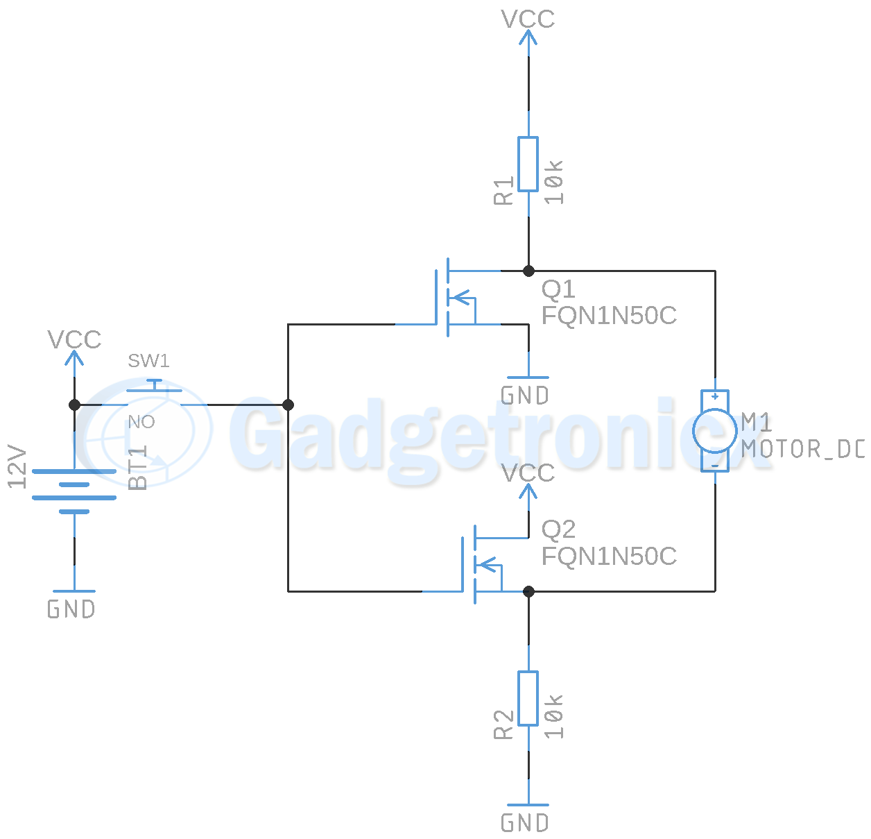
This project demonstrates how to control a stepper motor using a rotary encoder for input and an I2C LCD for parameter display. It allows users to adjust degrees of rotation, RPM, dead time (DT), and direction, making it a flexible system for stepper motor applications. Learn about the role of non-overlapping or complementary pulse width modulation (PMW) in DC motor control using an h-bridge circuit, taking into consideration PWM shoot-through and dead-time PWM. This discrete MOSFET stepper motor driver enables control of one bipolar stepper motor. It supports a wide 8 V to 50 V operating voltage range and can deliver up to 4 A continuous per phase without a heat sink or forced air flow (6 A max with sufficient additional cooling). The SPI interface allows configuration of the current limiting, step mode (9 step modes from full-step
Controlling Stepper Motors Using the Power IO Wildcard C library functions and MOSFET drivers for a four-phase six-wire unipolar permanent-magnet stepper motor 5V is for the logic, you can and should use higher voltage for the motors. The 8 MOSFETs are because the L298n is a dual-H brigge. It can control two DC motors separately in forward and reverse. For bipolar stepper motors you need two full H bridges. Since both sets of coils need to be able to run current in either direction.
Analog | Embedded processing | Semiconductor company | TI.com In this tutorial we will be controlling a solenoid with an Arduino and a transistor. The solenoid we have picked for this tutorial is our Plastic Water Solenoid Valve (perfect for controlling flow to a drip irrigation system) but this tutorial can be applied to most inductive loads including relays, solenoids, and basic DC motors.
INTRODUCTION Electronic motor control for various types of motors represents one of the main applications for MOSFET drivers today. This application note discusses some of the fundamental concepts needed to obtain the proper MOSFET driver for your application.
This is what is good about starting with no pre-defined libraries: you are in full control and can experiment and learn in the process. Example 2: It is not really necessary to use a micro controller or a special IC to control a stepper motor. So, here i present a very simple and basic full-step
using only arduino and transistors to drive steper motor?
This tutorial will teach you how to control stepper motors to get fine rotation and perfect angular control — a key skill for robotics projects. To turn the motor counterclockwise, the control sequence is reversed. The low power microcontroller control signals are interfaced to the motor via MOSFETs or power transistors to provide for the proper voltage and current requirements of the pulse sequence. The stepper motor may be used to position or scan robot sensors. As a note you can control 4 MOSFETS from a parallel port to drive a stepper in full step mode without anything special using High watt resistors. And no special driver.
The DRV8711 is a stepper motor controller that uses external N-channel MOSFETs to drive a bipolar stepper motor or two brushed DC motors. A microstepping indexer is integrated, which is capable of step modes from full step to 1/256-step. Single and dual motor driver carriers get your brushed DC motor projects up and running quickly using modern H-bridges with high-performance MOSFETs that deliver hundreds of watts in a compact package. Speed Controlling of DC Motor Using MOSFET: DC motors power everything from toothbrushes to robots. Controlling their speed and direction is crucial. In
I have a bipolar stepper motor (4 pins) and a darlington array. I want to use my arduino to control the stepper using the array. How do I do this? This is a stepper P-Channel MOSFET on the 12V (VCC) Side of the Load Let’s say you want to turn ON and OFF a 12V DC motor using an Arduino and a P-Channel MOSFET. The most intuitive way to archive this goal is to wire the MOSFET on the VCC side of the load (the motor in this case). The Tic T825 USB Multi-Interface Stepper Motor Controller makes basic control of a stepper motor easy, with quick configuration over USB using our free software. The controller supports six control interfaces: USB, TTL serial, I²C, analog voltage (potentiometer), quadrature encoder, and hobby radio control (RC). This version incorporates a TI DRV8825 driver, and male headers
Automotive manufacturers are increasingly turning to the use of Brushless Direct Current (BLDC) motors instead of brushed or stepper motors as they enable precise control over a wide dynamic range enabling more efficient, cooler running of higher power motor control solutions that are more reliable. Much of the growth in BLDC motor control is coming from previously Using a dual H-bridge isn’t the only way to drive stepper motors. You can also buy stepper motor drivers, which will have this dual H-bridge built
- Stepper Motor Control Basics with Arduino
- Arduino DC Motor Speed Control using MOSFET Transistor
- ESP32 Board for High-Speed Stepper Motor Control
- How to Use Adafruit MOSFET Driver: Examples, Pinouts, and Specs
- Determining MOSFET Driver Needs for Motor Drive Applications
Motors, Mechanics, Power and CNC 3 1964 May 6, 2021 Controlling a stepper via MOSFETs Motors, Mechanics, Power and CNC 8 6782 May 6, 2021 3.15v stepper motor, darlington array & arduino Interfacing 4 2628 May 6, 2021 Bipolar Stepper Motor w/ Darlington Array General Guidance 19 2387 November 22, 2021 DC motors power everything from toothbrushes to robots. Controlling their speed and direction is crucial. In this project, we’ll use an
ESP32 Board for High-Speed Stepper Motor Control
Hi, in this article, we are going to see the Stepper Motor Driver A4988 Pinout Diagram. Also, we will see the connection diagram for interfacing A4988 with the Arduino for stepper motor control. The A4988 Driver Module helps to precisely control stepper motors and it is widely used in 3D printers, CNC machines, and other applications accurate motor control is
As expected, the working of the project was verified. If you need to know more about this project, visit the official article explaining Arduino DC Motor Speed Control using a MOSFET transistor. Topics such as how to choose the right MOSFET for the project, simulations, and more are covered. Schematics to the following stepper motor video: Arduino MOSFET Drivers Coil connections The Arduino sketch below replaces the Stepper library which I found useless. It also includes I2C display as shown in the video. I consist of the command forward (int steps, int step_delay) and reverse (int steps, int step_delay). It also a motor off command. A potentiometer is connected
The Adafruit MOSFET Driver (Part ID: 5648) is a versatile module designed to control high-power devices using a low-power signal. This component is particularly useful in applications where microcontrollers, such as the Arduino UNO, need to drive motors, LEDs, and other high-current components. By leveraging the MOSFET Driver, users can efficiently manage power-hungry Do you ever need to drive something with more power than your microcontroller pin can handle? That is where MOSFETs come in. They are Learn how to control the speed of a DC motor using Arduino and a MOSFET. This guide covers component selection, circuit setup, coding, and practical demonstrations for building an efficient motor controller.
How are the pots to control the steppers? By position? By speed? Use a library like AccelStepper or MobaTools (my preferred) to assign a name to each motor. Then you can use the library functions to control each motor. Name each pot the same as its associated stepper. The pot’s pins and values could have names that associate each with a particular stepper. Or, Description Simple BLDC Motor Controller Circuit Using Irfz44n Mosfet Simple BLDC Motor Controller Circuit Using Irfz44n Mosfet IRFZ44N Mosfet IRFZ44 is one of the N Channel Mosfet Types and is in TO-220 sheath. IRFZ44 is N Channel Power Mosfet type. The IRFZ44 has a Gate-Source voltage of 60V and has a continuous output current of 48A.
I would like to drive a generic bipolar stepper motor using a L298 H-bridge. The application is a magnetic stir plate so I have no use for control of angle, step count, direction etc. I do however need to be able to control the rotation speed. The stepping sequence seem quite simple and straight forward. Assuming I would like to drive my motor without any stepper
- Contact • The David And Lucile Packard Foundation
- Cookies Clearing _ Clear Browser Cache And Cookies
- Contact Intercontinental Warsaw
- Contacteer Ons Compare Properties Spain
- Contours® Graco® V2 Infant Car Seat Adapter
- Controlling Mosquitoes In Your Garden
- Convert Millimetres Of Mercury To Inches Of Mercury
- Cookie Clicker Merch | Cookie Clicker Game Gifts & Merchandise for Sale
- Conti Lino L10 Click Waschtischarmatur Mit Ir-Sensor, Mit
- Cookie-Banner: Für Mehr Datenschutz Reichen Meist Zwei Klicks Aus
- Contacts Cosmos Hotel In Moscow