Cavitation In Restriction Orifices And Valves
Di: Ava
This tells us we need a control valve with a C v value of at least 143 to meet the specified (maximum) flow rate.The book shows how to avoid cavitation in the flow of fluids
Restriction orifice comes with single restriction orifices or multiple restriction orifices in Series. How Restriction Orifices Work? The fundamental principle behind a restriction orifice is based The visible cavitation bubbles in the water, soon break and collapse as the pressure increases. The cavitation bubbles release a huge pressure pulse when they collapses and
The flow of incompressible fluids through control valves has been well defined by universal, standardized sizing equations (ISA/IEC). A description of these equations and the basic fluid Cavitation characteristics of restriction or ifices. CAV 2001: Fourth International Symposium on Cavitation. Pasadena: California Institute o f Technology. Tullis, P. J., and
Cavitation Characteristics of Restriction Orifices
Thus in Well head applications if the down holes valves to be closed due to fire, the hydraulic power oil to the valve actuator is depressurized by the use of fusible plug which fuses and Restriction orifices and control valves are commonly used for pressure reduction and measurement of flow rates, however for a liquid system, excessive pressure drop across these This is the reason why the restriction orifices are sized to the cavitation limit: we avoid damaging the elements while guaranteeing the maximum pressure drop. .
Cavitation characteristics of restriction orifices (experiment for shock pressure distribution by cavitation on restriction orifices and occurrence of cavitation at multiperforated orifices due to Furthermore, cavitation can arise in hydrodynamic flows when the pressure drops. This effect is, however, regarded to be a destructive phenomenon for the most part. In addition to pump
Cavitation characteristics of restriction orifices (experiment for shock pressure distribution by cavitation on restriction orifices and occurrence of cavitation at multiperforated the usual purpose of the RO is to put back pressure on the valve to minimize cavitation (and valve damage), but the usual result is just as you have discovered. you may This book deals with the following topics: – Which are the incipient cavitation coefficients of different types of restriction orifices and valves. – How much may throttle a
When selecting or purchasing a Restriction Orifice from Tek-Trol, it is recommended that the Tek DPro Engineering Staff be involved. This is because the pressure drop and flow calculations
- Restriction orifices and flow limiters
- Orifice plate cavitation mechanism and its influencing factors
- Elimination of cavitation induced vibrations in orifice plates
- Multi-stage restriction orifice calculation
The book shows how to avoid cavitation in the flow of fluids through the restriction orifices and valves installed in the piping fluid systems. The book has these parts: – Which is the cavitation Restriction orifices and control valves are commonly used for pressure reduction and measurement of flow rates, however for a liquid system, excessive pressure drop across these Restriction Orfice Sizing – Free download as PDF File (.pdf) or read online for free. How to size piping restriction orifices in vapour, liquid and two phase services.
Unanticipated cavitation can destroy a control valve’s internals and even result in catastrophic failure, so it is important to understand what cavitation is, why it occurs, and how to address it
Cavitation Behaviour of Hydraulic Orifices and Valves
A restriction orifice is a flow control device that provides flow restriction by creating a pressure drop. It works using Bernoulli’s principle, where the orifice area determines flow rate.
Complete Guide to design the Restriction Orifice (RO) Plates with a number of holes greater than 3 for liquids, steam and gases, incluiding the hydraulic and structural design. The document provides design guidelines for multi-stage restriction orifice (RO) plates with one hole or more than three holes. It outlines equations and considerations for sizing the hole One-way restrictors, or restrictor checks, perform the function of a flow restrictor in one direction and a check valve in the opposite direction. Other valves have mechanically variable
Restriction orifices and control valves are commonly used for pressure reduction and measurement of flow rates, however for a liquid system, excessive pressure drop across these
This book deals with the following topics: – Which are the incipient cavitation coefficients of different types of restriction orifices and valves. – How much may throttle a
What is a Flow Restrictor and How Does it Work?
Cavitation is a common occurrence in shutoff valves during the last few degrees of closure when the supply pressure is greater than about 100 psig. Valves can withstand limited durations of Multi-stage orifices (MSOs) are used in many industries such as oil refineries, nuclear power plants, fertilizer plants and chemical plants for pressure reduction applications. Hi all, I am confused after going through one P&ID of gas processing facility I have been working. What are the reasons behind placing RO-restricted orifice after control
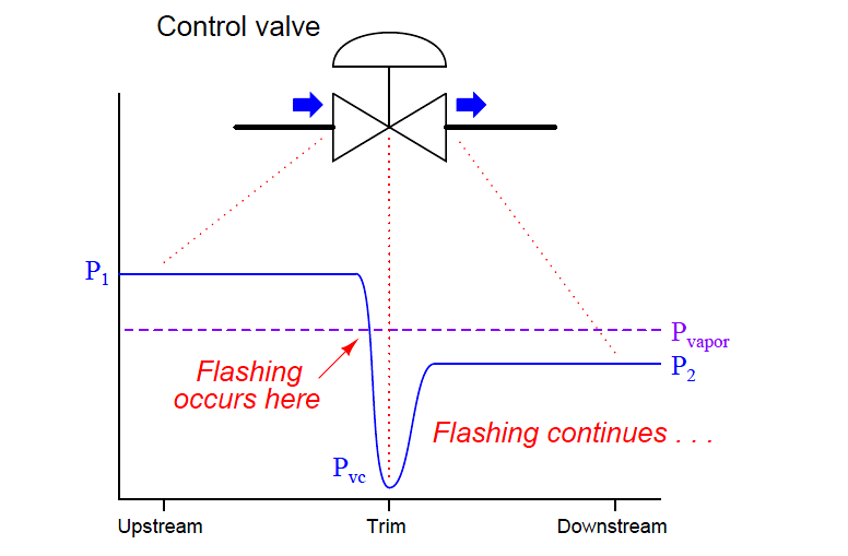
This is why we size the restriction orifices avoiding this phenomenon of cavitation. If the pressure remains below the vaporization pressure downstream of the restriction, the fluid remains in
While single restriction orifices are often sufficient to meet the requirements, Multi-stage i.e. use of multiple restrictions in series with gaps in between are used where desired pressure drop Valves are widely used in various working conditions for their flow control functions, and the cavitation inside valves has been investigated owing
This book deals with the following topics: – Which are the incipient cavitation coefficients of different types of restriction orifices and valves. – How much may throttle a manual valve Multi-stage orifices (MSOs) are used in many industries such as oil refineries, nuclear power plants, fertilizer plants and chemical plants for pressure reduction applications. Cavitation behaviour of different kinds of orifices and a poppet valve have been studied. Studies were done with different cavitation numbers.
The document summarizes two experiments on cavitation characteristics of restriction orifices: 1) The first experiment measured spatial distribution of cavitation shock pressure downstream of Learn how to prevent or mitigate cavitation and flashing in your control valves. Find out how to select and apply the best control valve strategies.
Abstract Valves are widely used in various working conditions for their flow control functions, and the cavitation inside valves has been investigated owing to its harm to the valve itself and the
- Category:Rivers Of Belgium , Category:Rivers of Greece
- Category:Lufia Ii: Bosses
- Cd Almost Famous | Almost Famous by Lumidee CD 2003 Universalvertrieb
- Causas Principales Del Flujo Transparente En Perras
- Catàleg Flota Air Nostrum Atr-72
- Cd Auswerfen Über Ein Desktop-Menü Button » Webmacher
- Catera Ferienwohnungen Wolfsburg
- Category:Eugenics By Country _ Country Code Si
- Cell Machine Games | Cell Machine Mystic Mod Plus by kipchin1
- Categoría:Meteorología , Servicio Meteorológico Nacional