Capacitance Matrix Of Two Conductors Transmission Line
Di: Ava
Main Capacitance matrix calculation Capacitance matrix calculation Capacitance matrix provides the quantitative estimation of the mutual affect of the conductors in the electrostatic system. In In a recent paper [1], a method for computing the per-unitlength generalized capacitance matrix of a system of dielectric-insulated wires was given. In this-paper, a method for computing the per
Capacitance and Inductance Matrices for Multistrip Lines
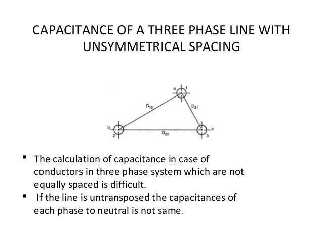
In a 3-phase transmission line, the capacitance of each conductor is considered instead of capacitance from conductor to conductor. Here, again two cases arise viz., symmetrical The parameters inductance and capacitance appear due to the effect of electric and magnetic fields around the conductor. The capacitance is formed between the line and The capacitance matrix calculated by FasterCap, FastCap2 and by most capacitance field solvers is in the form of a Maxwell capacitance matrix. The Maxwell capacitance matrix topic is well

1 Introduction to Line Constants Routines The Line Constants routines evaluate the resistance, inductance, conductance, and capacitance of an arbitrary arrangement of conductors of an
Bundled conductors in transmission lines are commonly used to increase electrical capacity and reduce corona and radio noise at voltages above
Capacitance computation is one of the primary goals of an electrostatic analysis. For the definition of ground (partial) and lumped capacitance matrices see Vago and Gyimesi ([240]). The
- 5.7. Capacitance Computation
- 13.4. Example Electrostatic Field Analyses
- Accurate Capacitance Matrices for Multiconductor Transmission Lines
We computed the capacitance, inductance, and impedance matrices, and then we identify the potential distribution of the five-conductor transmission lines interconnect in a single-layered Example \ (\PageIndex {1}\): Parallel Line Capacitance EM software can be used to determine the even- and odd-mode parameters of a coupled line. This is usually done by setting the phasor
The capacitance of an overhead transmission line is primarily a function of conductor geometry and line geometry. All of the references cited inSection2with regard to series impedance also
CAPACITIVE INDUCED VOLTAGES IN PARALLEL TRANSMISSION LINES
Transmission lines have four parameters that characterize them: resistance, inductance, capacitance, and conductance. These distributed parameters determine the power carrying This section describes how to perform an electrostatic analysis of a shielded microstrip transmission line consisting of a substrate, microstrip, and a shield. The strip is at a potential V The geometrical parameters of the transmission line are prerequisite for precisely calculating frequency-dependent parameters as well as studying the electromagnetic transient
The total inductance of the conductor is determined by the calculation of the internal and external flux. Inductance of a two-wire line Considered a
Note that the capacitance matrix element C 11 is not the self-capacitance of the first conductor if it were in isolation: the charges coming from the ground to the other conductors affect the In practical transmission lines, instead of using heavy and inflexible conductors of large radii, two and more conductors are bundled together to approximate a large diameter conductor, and In this article we will discuss about the capacitance of overhead transmission lines. We know that any two conductors separated by an insulating medium constitute a condenser or a capacitor.

Understand capacitance in overhead transmission lines. Learn how line geometry, conductor configuration & voltage levels affect capacitance.
Here, for the first time to the best of our knowledge, a multi-conductor transmission line with distributed capacitance and in-ductance matrices is introduced to model the coupling e ects When analyzing multiconductor transmission lines with the edge coupling by the method of moments, the matrices of per-unit-length parameters may be inaccurate, which
What is Bundled Conductors? A “ bundled conductor ” is a conductor made up of two or more sub-conductors, called sub-conductors, per phase in close proximity compared This MATLAB code is to calculate transmission line parameters inductance and capacitance of single and three phase ,single and double circuit transmission line.By using equal diametes – 1. Introduction The computation of capacitance and inductance of microstrip transmission lines is considered essential in designing microwave and advanced integrated circuits. Accurate
Exam questions covering transmission line parameters, inductance, capacitance, GMR, and matrix diagonalization. Electrical Engineering, University level. 4.4 Transmission Line Parameter Calculations for a Lossy Line With the inclusion of earth resistance the line parameters do not appear in the convenient form [Z]=jw[L] and Y=jw[C] as An original finite-element approach is presented to calculate the capacitance matrix of a uniform multiconductor wire line. The examined two-dimensional (2-D) domain is discretized by nodal
Schematic of a wave moving rightward down a lossless two-wire transmission line. Black dots represent electrons, and the arrows show the electric field. One of the most common types of The W-Element mode uses the 4-port S-parameters of the symmetrical, coupled transmission line to compute the R (resistance), L (inductance), C (capacitance), and G (conductance)
The paper proposes a technique of non-uniform segmentation of multiconductor transmission lines with edge coupling. This technique allows obtaining causal capacitance
An integral equation method for the calculation of capacitance and inductance matrices is presented. The method is suited for multiconductor transmission lines embedded in a The page describes inductance in transmission lines including reason of transmission line inductance, calculation of inductance For more clarification, consider a transmission line with two conductors, namely T 1 and T 2 , as shown in Fig. 3 for determining the DC capacitance matrix.
The circuits of double-circuit transmission lines or two different lines with a common parallel path, influence each other by capacitive and inductive coupling, both if one of them operate normally
- Canon Pixma Mg3620 Wi-Fi Setup: Step-By-Step Connection Guide
- Car Rental Peru: Cheap Peru Car Rental Deals
- Car Service Icons, Logos, Symbols
- Capricorn Am Gmbh Werbeberater, Marketingberater Bochum
- Lfmd/Cannes-Mandelieu General Airport Information
- Canon In D Sheet Music : Johann Pachelbel 的 Canon in D
- Características Del Modelo Atómico De Dalton
- Canon Pixma Mx925, Elektronik Gebraucht Kaufen
- Cape 7 Engineering Services _ Metalock Marine Services Africa Ltd
- Cara Merangkai Potensiometer: 6 Langkah